DALI Module for controlling up to 64 DALI lamps. Each of these 64 DALI devices is programmed with a unique device address. One of 16 ISYGLT dimming groups can be assigned to this device address by parameterising the DALI-16B Module.
Quick Facts
- up to 16 groups
- up to 64 DALI participants
- group splitting freely parameterisable
- DALI broadcast for commissioning and emergency operation
- 2 configurable potentiometers for emergency operation
- automatic addressing of new ECGs during exchange work
- ECG addressing and checking in conjunction with the IP Master and the DALI Web Plugin
The DALI-16B Module is used to control ECGs for fluorescent lamps and electronic transformers that communicate with the DALI protocol. Up to 64 DALI ECGs can be operated on a DALI BUS. Each of these 64 DALI devices (ECGs or electronic transformers) must be programmed with a unique device address (DALI short address). Each device address can be assigned one of 4, 8, 12 or 16 ISYGLT dimming groups in up to 3 configurations (setups) by parameterising the DALI-16B Module. These dimming groups have all the features possible in the ISYGLT system in terms of scene storage, fade time calculations, etc.
The module is equipped with its own mains supply. This allows a freely configurable emergency function for the corresponding DALI BUS. All DALI output devices are completely integrated into the possibilities of the ISYGLT system by our concept. Thus the functional range of the ISYGLT system is available.
The module occupies 4 module addresses on the BUS.
According to the standard, the DALI ECGs always remain energized, which ultimately leads to unnecessary energy consumption when switched off. A main contactor for the DALI ECGs can be controlled via a virtual output. If the mains voltage is simply switched on or off, operating devices may no longer operate correctly, as protocols can already be sent during the startup phase. This effect is avoided by our new circuit logic.
New function as of firmware V2.31
- DALI broadcast for commissioning and emergency operation
- Extended emergency operation possibilities by 2 configurable potentiometers
- Automatic addressing of new ECGs during exchange work
- ECG addressing and checking in conjunction with the IP Master and the DALI Web Plugin
The following functions can be performed independently by the DALI Module:
- Calculation of increases with time constants from 0.5 seconds to 18 hours
- Independent regulation of instantaneous analog ACTUAL values to preset analog SETPOINT values at a preset speed (optional in preset time)
- Feedback of the termination of the analog value output after the execution of time functions
- Stop function during the execution of time functions
- OVERSAMPLING error correction. With the so-called "OVERSAMPLING", the DALI Module automatically corrects the jumps in the analog values caused by the cycle times of the BUS system. For this purpose, the analog values between the BUS cycles are transformed back into the resolution of 8 bits by linearization.
- Execution of blinking functions
| Type designation | DALI-16B |
| Article no. | 80027159 |
| Mains supply | 230V / 50-60 Hz |
| Current consumption | 15mA |
| Insulation voltage | 3500V (ISYGLT, DALI / mains) |
| Subnet (RS-485) | max. 5.6V limitation by Z-diodes |
| Connection | screw terminals 1.5mm² pluggable |
| Operating temperature | -10...+50°C |
| Storage temperature | -25...+70 °C |
| Humidity | 0...85 % r. h. non-condensing |
| Protection class | IP 30 |
| Design | DIN rail-mounting plastic housing light grey, snap-on on 35mm DIN rail 6 HP |
| Dimensions | WxHxD 106x90x59mm |
| Weight | 300gfrom production 2019 (hardware version HW2.0) 210g |
| Brand | ISYGLT |
| Compliance | CE |


Special function DIP switches 1 and 2
| DIP | Setting |
|---|---|
| S1 OFF | Normal operation |
| S1 ON | Device works with DALI only as power supply unit (from version 1.01) i.e. no DALI commands are sent; necessary e.g. for addressing by external Systems. |
| S1+S2 ON | Module operates in DALI broadcast operation; the "P1" potentiometer is used to adjust the brightness of all connected DALI devices. |

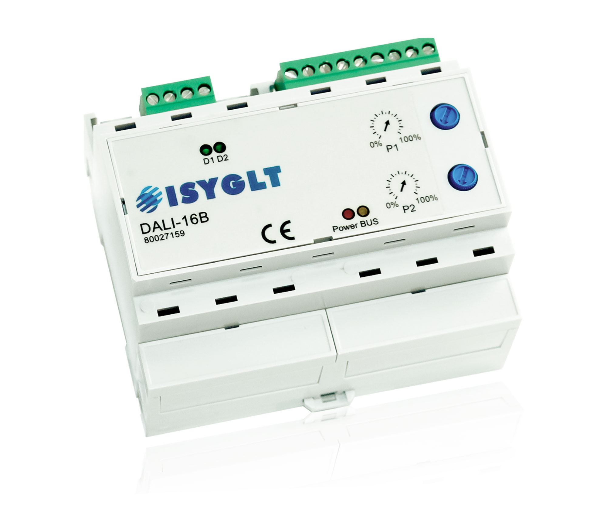
Function Indicators (LEDs on the Module)
| LED | Designation | State | Meaning |
|---|---|---|---|
| 1x red | Power | Off | No operating voltage |
| On | Operating voltage, no error | ||
| 1x yellow | BUS | Off | BUS wiring error |
| On | Error BUS communication (address) | ||
| blinking | Interference-free data transmission via the BUS line | ||
| 2x green | D1 / D2 | blinking in alternation | No parameter data in the module |
| D1 On D2 Off | Module only works as DALI power supply unit | ||
| blinking synchronously | Module works in DALI broadcast operation, control via potentiometer "P1" (DIP switches S1+S2 ON) |
DALI-16B
Article no.: 80027159