The Universal Dimmer is suitable for the reliable operation of high-voltage lamps, magnetic transformers, electronic transformers, ESL and LED retrofit lamps. Two separate dimmer outputs are available, each of which can be loaded with 700W. By configuration and parallel connection of the outputs the dimmer is loadable with 1x1400W.
Each channel can be parameterised separately for the corresponding load type (leading edge/trailing edge mode). The dimmer automatically checks the connected load by carrying out a short test after first applying the operating voltage to check whether the connected load can be operated with the desired setting.
The dimmer operates with an internal dimming resolution of 16 bits and thus meets the highest demands.
The factory-set properties such as dimming curves, minimum and maximum limits can be changed and optimised by the user himself.
Control types of the dimmer:
- ISYGLT BUS protocol
- DMX512 8Bit and 16Bit
- stand-alone: 0-10V, 1-10V, push-button (single-button dimmer)
- internal potentiometers
- to the BUS protocols ISYGLT or DMX512, the internal potentiometers and voltage inputs can be parameterised as priority, merge operation or for the BUS failure
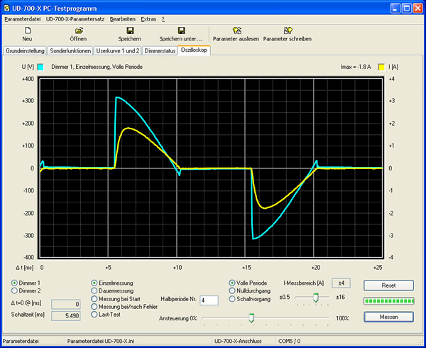
For ISYGLT users, the functions can be parameterised as usual in the ProgramDesigner. A free software tool is available for standalone and DMX users. This allows the dimmer to be optimised per parameter via USB or RS-485 data connection and internal data such as temperatures, voltages, peak currents and power to be displayed. An oscilloscope function is also integrated as a new feature. For the first time, the user now has an aid for displaying the current load - without dangerous measurements on the mains voltage!
An inspection of unknown light sources - e.g. new retrofit lamps - is therefore possible without additional measuring equipment. All you need is the connected UD-700-X2 dimmer, a USB cable (USB type A to Micro B m/m) and our free software.
| Type designation | UD-700-X2 |
| Article no. | 80026503 |
| Mains supply | 230V / 45 to 65 Hz |
| Mains fuse | 1 x 230V automatic or GL fuse 10A |
| Output |
2 x 230V short-circuit proof, 10W - 700W/VA per channel or 1x 1400W/VA coupled |
| Power loss | <0.5 ... 6W (Stand-by ... full load) per channel - total 12W at 2x700W load |
| 1 (0)-10V |
sink current at 1-10V = 0.54mA or source current at hardware option "0-10V" = 0.14mA at 71kOhm |
| Insulation voltage | 3500V (ISYGLT-BUS / mains) |
| Short-circuit protection |
electronic overload protection by current measurement short-circuit cut-off within 10 milliseconds |
| Subnet (RS-485) | max. 5.6V limitation by Z diodes |
| Connection | screw terminals 1.5mm² pluggable |
| Operating temperature |
-10...+45°C > at +50°C max. 60% connectable power > at +55°C max. 50% connectable power > +60°C max. 30% connectable power |
| Storage temperature | -25...+70 °C |
| Humidity | 0...85 % r.h. non-condensing |
| Protection class | IP 30 |
| Protection class | I |
| Design | DIN rail housing |
| Dimensions | WxHxD 106x90x59mm rail-mounted device (6 HP) |
| Weight | 300 g |
| Brand | ISYGLT |
| Compliance | CE |


DIP switches in stand-alone operation
Setting options via DIP switches
| Function | Operating mode |
|---|---|
| U input 1-10V | Control via digital potentiometer from switch manufacturer, or 1-10V dimmer coupler (behaves like an ECG from fluorescent lamps - the 10V for the 1-10V dimming is supplied by the dimmer) |
| U input 0-10V | Control via external control e.g. PLC with 0-10V (0-10V voltage is supplied from the PLC) |
| A/B/C/D | See table below |
| Res. | Not assigned in this operating mode |
| Channel 1+2 coupled | The dimmer works with 1 channel, power 1x1400W. Connector between outputs LD1 and LD2 required. |
| Channel 1+2 separate | The dimmer works with 2 channel, power 2x700W. The LD1 and LD2 outputs must not be connected. |
| Single-button dimmer | Control via standard buttons on terminals UE1 and UE2 against GND Press briefly = on/off, press longer = dim |
| Analog 0(1)-10V | Analog control - in this position the DIP switches 3 are enabled for the selection 0-10V or 1-10V. |
A/B/C/D DIP switch - Operating mode setting for DMX512 and stand-alone operation
| DIP-A | DIP-B | Operating mode |
|---|---|---|
| OFF | OFF | Automatic operating mode switching, the start value is predefined with the PC program on the "General" tab. |
| ON | OFF | Trailing edge |
| OFF | ON | Leading edge |
| ON | ON | NonDim |
| DIP-C | DIP-D | Setting dimming characteristics such as min-max values, curves, etc. (see PC program for the UD-700-X2) |
|---|---|---|
| OFF | OFF | Parameters of the 1st column, curve P-linear ("General" in the PC program) |
| ON | OFF | Parameters of the 2nd column, curve DALI ("General" in the PC program) |
| OFF | ON | Parameters of the 3rd column, curve t-linear ("General" in the PC program) |
| ON | ON | Parameters of the 4th column (with preheating setting for ESL) ("General" in PC program UD-700-X2) |
Function Indicators (LEDs on the Module)
| LED | State | Designation | Meaning |
|---|---|---|---|
| red | Off | POWER | No operating voltage |
| On | Operating voltage, no error voltage supply | ||
| blinking | Too high mains voltage (>400Vs) | ||
| 3x blinking | No valid parameters available | ||
| yellow | Off | BUS | Error in BUS wiring / no BUS signal detected |
| On | BUS is active, but communication processor receives no data DMX: Data for the set address are not transmitted (telegram too short) or data format is wrong RS485 test: Set address or data format is wrong | ||
| blinking | Interference-free data transmission / communication processor receives data | ||
| 2x green | Off | D1, D2 | Output "OFF", no error |
| On | Output "ON", no error | ||
| blinking evenly | Warning/switching off when temperatures are too high: Communication processor: 65°C / 75°C MOSFET housing: 95°C / 105°C | ||
| 1x blinking + pause | Message in case of overload: 1. When exceeding the max. permitted peak current (>15A) 2. When the limit values for power loss (>8W/channel) or peak current (>10A) are reached | ||
| 2x blinking + pause | Message after switch-off at voltage peaks >450V | ||
| 3x blinking + pause | Failure of communication with dimmer processor |
Parameter Configuration and Verification
This dimmer now offers separate parameterization options for ISYGLT and DMX-512/Standalone modes for the first time.
- Parallel connection of two outputs, each 700W/VA, to achieve a total of 1400W/VA
- Phase control (phase-cut or phase-absorption)
- Adjustment of dimming curves
- Feedback on dimmer status (diagnostic messages)
- Definition of emergency mode in case of bus failure
For the DMX-512 and Standalone modes, detailed descriptions of the available options can be found in the documentation: UD-700-X2_PC-Software.
When the dimmer is operated within an ISYGLT system with a master module, additional optimization through parameterization is possible in the ProgramDesigner. The debugger function in the ProgramDesigner allows you to easily monitor the current behavior of the dimmer and manually simulate dimming values.
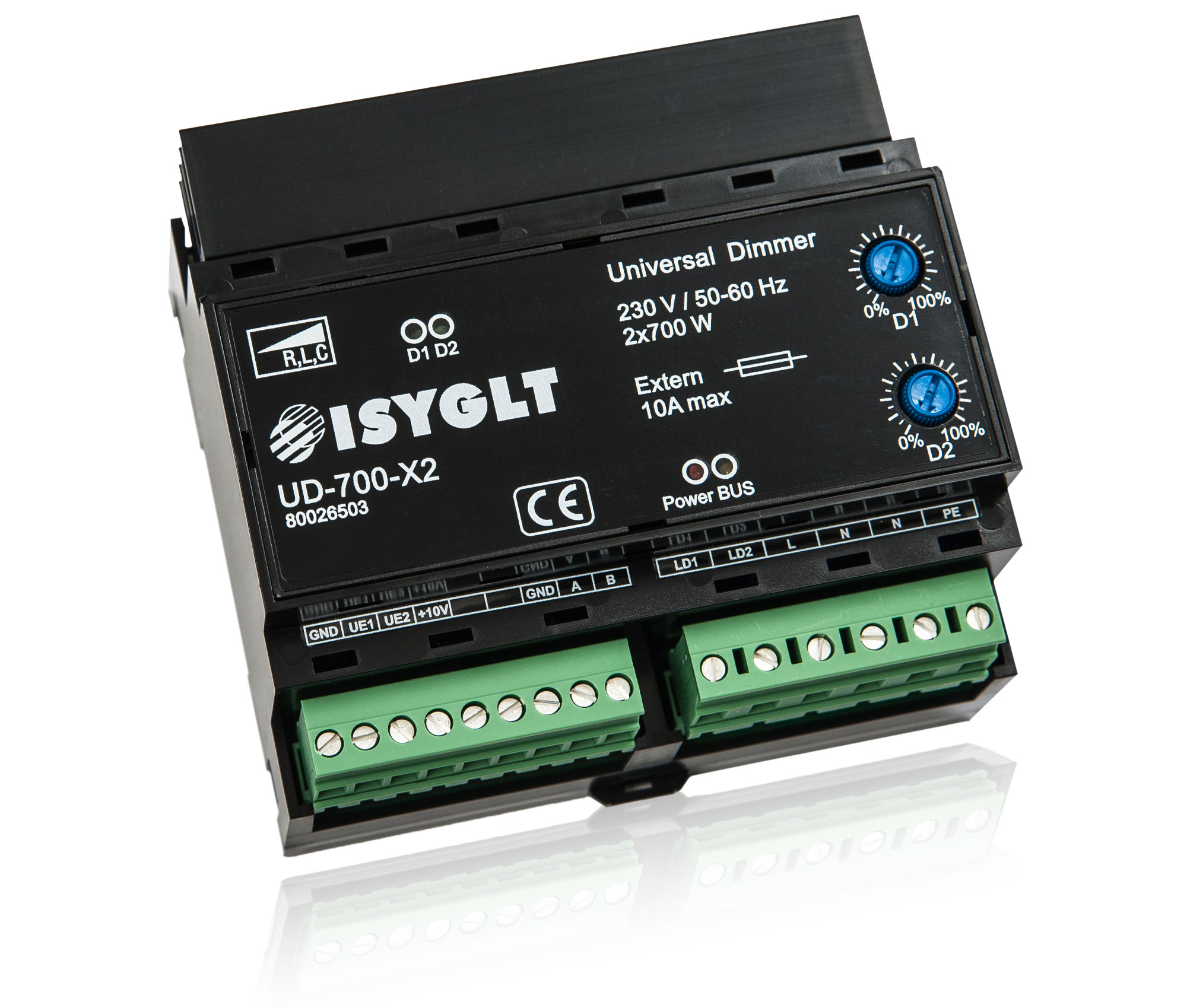
9-pole plug left
| GND | Reference potential (Ground) for the voltage inputs (0-10V) and BUS RS485 (internally bridged with the seventh terminal) |
| UE1 | Control voltage input for the dimmer output LD1 (emergency function) |
| UE2 | Control voltage input for dimmer output LD2 (emergency function) |
| +10V | Power supply for external potentiometer(s) |
| Res. | |
| Res. | |
| GND | Reference potential (Ground) for the voltage inputs (0-10V) and BUS RS485 (internally bridged with the first terminal) |
| A | Subnet (BUS A, RS-485) |
| B | Subnet (BUS B, RS-485) |
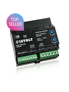
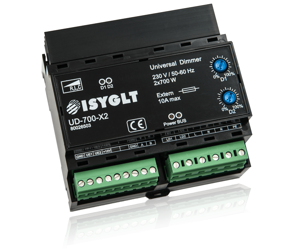
UD-700-X2
Article no.: 80026503