The Analog Output Module is equipped with 4 independent analog outputs. The outputs have an output voltage range from 0 to 10V with 8 bit resolution. The output voltage ranges can be reprogrammed via software within the limits of 0 to 10V (e.g. 1 to 10V for the connection of standardised ECGs). The voltage outputs are galvanically isolated from the subnet and the operating voltage of the module. There is no potential separation between the 4 outputs. The outputs can be loaded as current source or current sink with 20mA per output. The 0-10V and 1-10V control is easily possible with this module. The module DA-04-VX can be set from speed calculation to absolute time calculation by parameterisation per channel. All imaginable control tasks from individual light dimming to the use for complex lighting scenarios can be easily implemented.
The following functions can be performed independently by the DA module:
- Calculation of rise times from 0.5 seconds to 12 hours
- Autonomous running from current analog ACTUAL values to preset analog SETPOINT values at a preset speed (optionally in a preset time)
- Feedback "Analog value reached" after execution of time functions
- Stop function during the execution of time functions
- OVERSAMPLING error correction (With the so-called "OVERSAMPLING", the DA module automatically corrects the jumps in the analog values caused by the cycle times of the BUS system. For this purpose, the analog values between the BUS cycles are transformed back into the resolution of 8 bits by linearisation. This prevents, for example, flickering when controlling dimmers. During programming the OVERSAMPLING is called SOFT function.)
- Execution of blinking functions
- Adaptation to different light sources and dimmers
- Calculation of defined and definable curves
- Calculate minimum and maximum settings per channel to use full 8 bit width
- Complex emergency operation function
| Type designation | DA-04-VX |
| Article no. | 80027003 |
| Operating voltage | 18V to 35V DC or 18V to 27V AC |
| Current consumption |
max. 120mA at 35V and full load of the outputs max. 200mA at 18V and full load of the outputs |
| Output voltage | 4 analog channels, 8 bit resolution 0-10V |
| Output current | 20mA per channel, operation as current source or current sink (total 80mA >> can also be divided between the outputs, e.g. output 1 = 70mA, output 2 = 5mA, output 3 = 4mA, output 4 = 1mA) |
| Isolation voltage | 300V (subnet / analog outputs) |
| Subnet (RS-485) | max. 5.6V limitation by Z-diodes |
| Connection | screw terminals pluggable and P-COM connectors |
| Operating temperature | -10...+50°C |
| Storage temperature | -25...+70°C |
| Humidity | 0...85% r. h. non-condensing |
| Protection class | IP30 |
| Design | DIN rail-mounting plastic housing light grey, snap-on on 35mm DIN rail 3 HP |
| Dimensions | WxHxD 53x90x59mm |
| Weight | 200g |
| Brand | ISYGLT |
| Compliance | CE |


Function Indicators (LEDs on the Module)
| LED | Designation | State | Meaning |
|---|---|---|---|
| red | Power | Off | No operating voltage |
| On | Operating voltage, no error | ||
| yellow | BUS | Off / On | Error BUS |
| blinking | Interference-free data transmission via the BUS line | ||
| green | Regeln | blinking | Signals the regulation of the outputs (LED blinks until the desired final value is reached) |
Parameterisation with ProgramDesigner
In the ISYGLT ProgramDesigner there are various parameterisation possibilities:
- Minimum-maximum values per channel
- Function of the feedback bit per channel
- Definition of the curve calculation
- Definition of the emergency operation
- Setting the dimming curves
- Emergency operation in case of BUS failure
Information on long-term dimming with regard to time definition: Long-term dimming
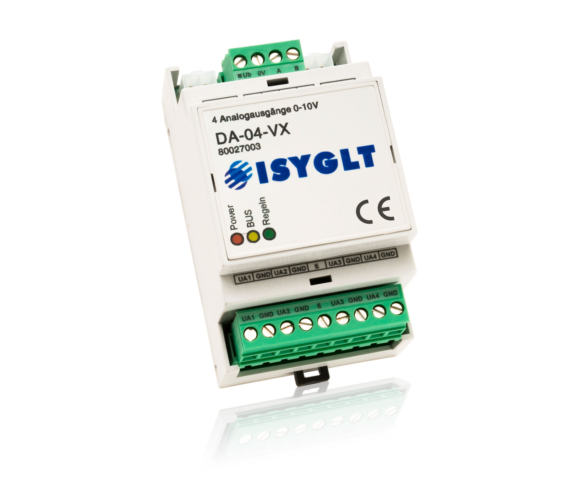
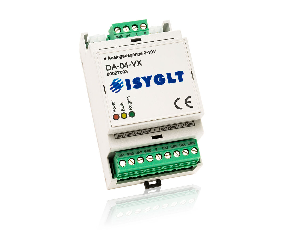
9-pole plug below
| UA1 | Analog output channel 1 |
| GND | Reference potential (ground) for analog outputs (4x internally connected) |
| UA2 | Analog output channel 2 |
| GND | Reference potential (ground) for analog outputs (4x internally connected) |
| E | Emergency operating input |
| UA3 | Analog output channel 3 |
| GND | Reference potential (ground) for analog outputs (4x internally connected) |
| UA4 | Analog output channel 4 |
| GND | Reference potential (ground) for analog outputs (4x internally connected) |
DA-04-VX
Article no.: 80027003