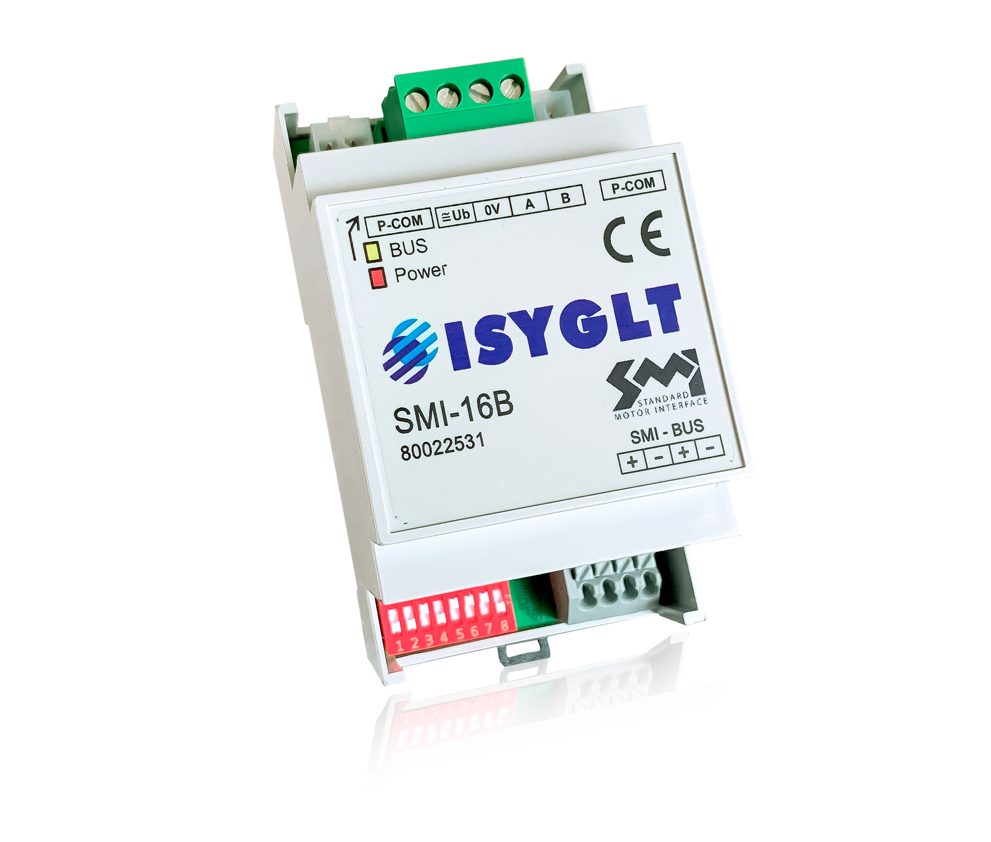
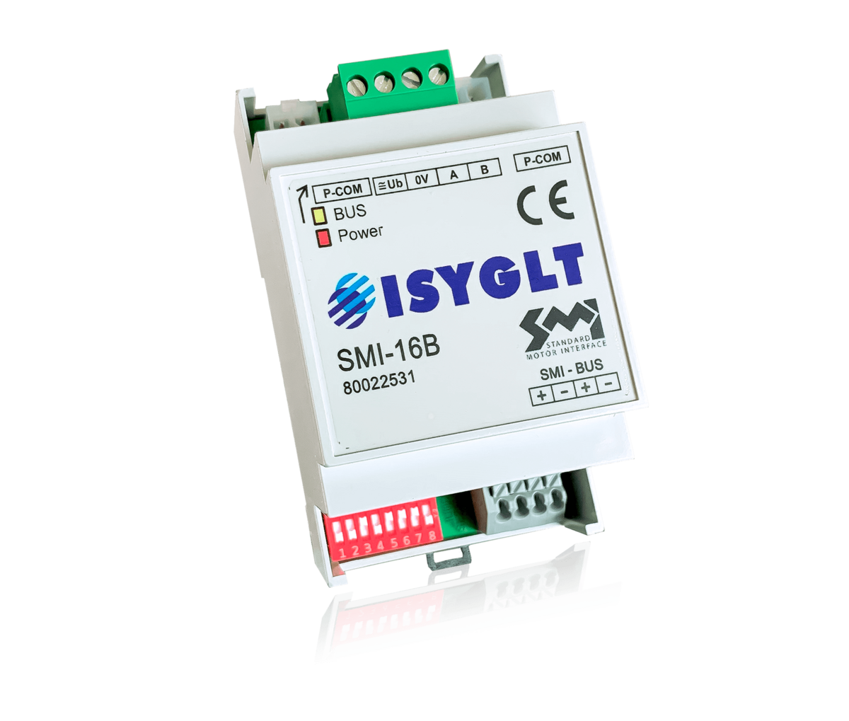
The ISYGLT SMI-16B module is an interface to the SMI-BUS (standard motor interface). The SMI-BUS was specially developed for perfect control of sun protection, shading and blackout drives. The connection cable is standardized as a 5-wire cable and contains the 230V power supply for the motor (L, N, PE), as well as 2 wires for the SMI BUS (I+, I-). Up to 16 SMI drives can be controlled individually or in groups on this BUS. The maximum cable length of the SMI BUS is defined as 350 m with free topology.
Applications
Roller blind control
Manual or automatic movement of the blinds - positions are also possible
Venetian blind control
Manual and automatic positioning of blinds and setting of slat angles. Slat angles can also be set again after position movements.
Automatic sun protection, shading and glare protection control
In conjunction with the sun position calculation, date, time, geo-position and weather sensors, fully automatic glare protection and shading control is very easy.All the settings required for this are possible as usual in the ISYGLT program designer using parameters.
The SMI-16B module occupies 4 module addresses in the master. The address of the first module is set on the DIP switch.
| Type designation | SMI-16B |
| Item number | 80022351 |
| Operating voltage | 21V to 26V DC |
| Current consumption | 50mA at 24V |
| Subnet (RS-485) | max. 5.6V limitation by Z-diodes |
| Connection | screw terminals 1.5mm² pluggable, SMI-BUS Push-in-terminal 1.5mm² |
| Operating temperature | -10...+50°C |
| Storage temperature | -20...+70°C |
| Humidity | 0...85 % r. h. non-condensing |
| Protection class | IP 20 |
| Protection rating | II |
| Design | DIN rail-mounting plastic housing light grey, snap-on on 35mm DIN rail 3 HP |
| Dimensions | WxHxD 53x90x59mm |
| Weight | 90g |
| Brand | ISYGLT |
| Compliance | CE |


Parameterisation with ProgrammDesigner
You will find instructions for commissioning in the parameters and in the ProgrammDesigner help. The motor ID must be known to identify the drive. This is attached to the motor and is usually enclosed several times as a sticker. This ID is simply entered in the gateway and transferred via parameter transfer. The motor can now be controlled via the ISYGLT system.
The other functionalities can also be seen in the software.
SMI-16B
Article no.: 80022531