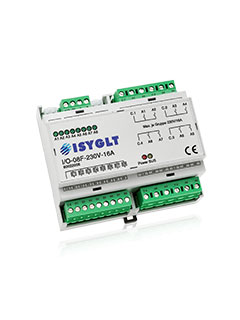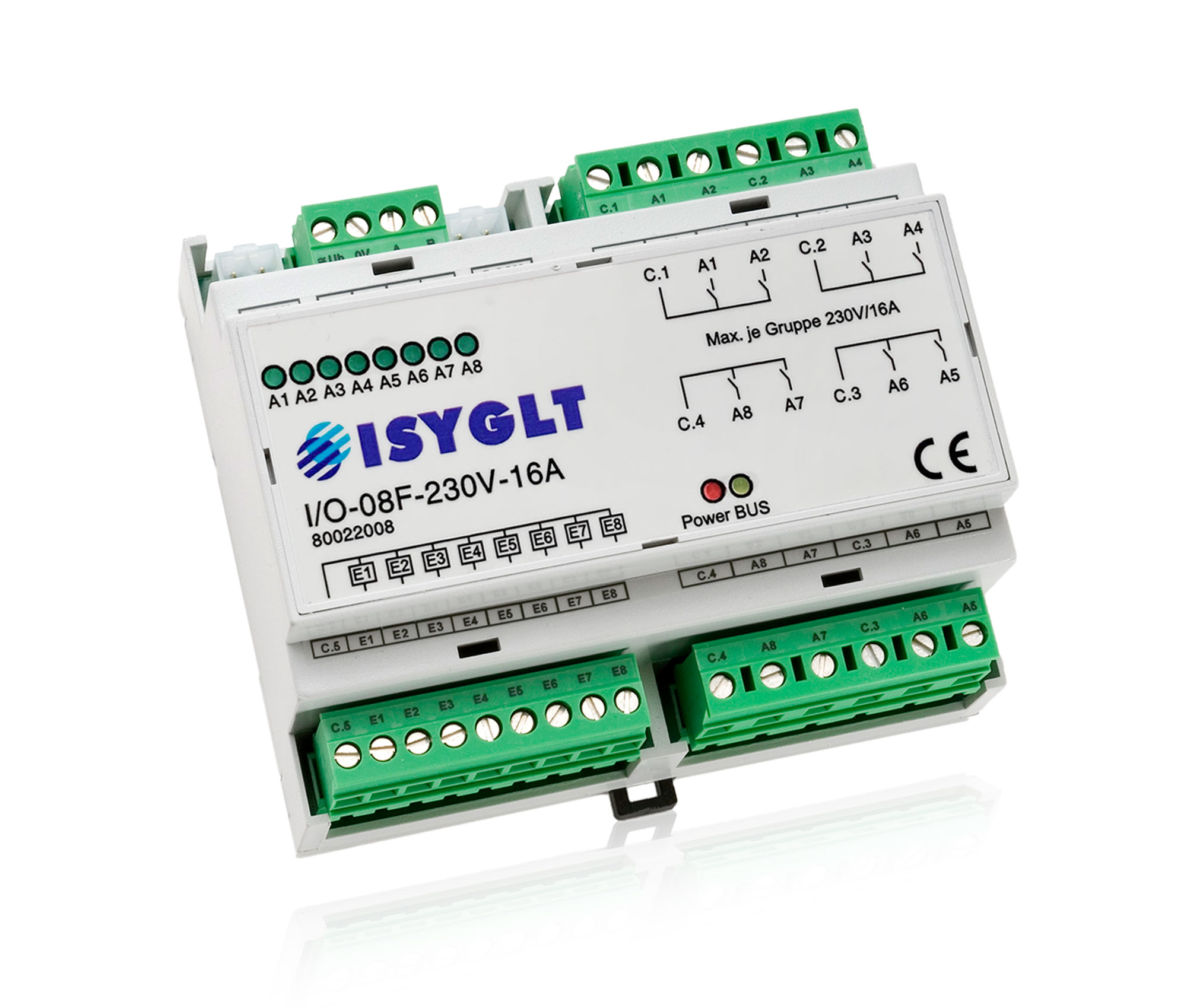
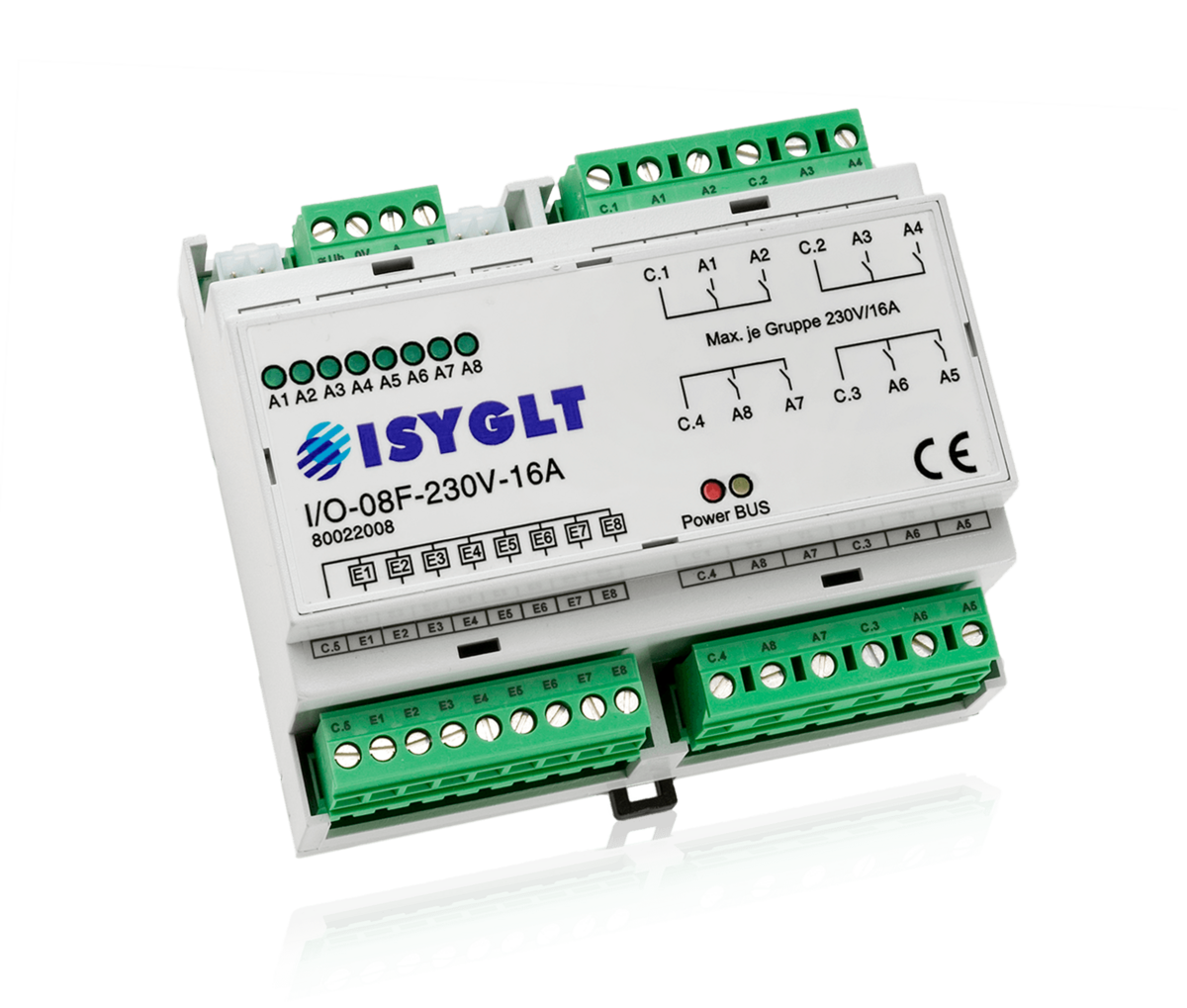
With the I/O module I/O-08F-230V-16A, 8 circuits with a maximum of 230V/16A (2 contacts each on a common root) can be switched bistably. This is a special feature of the module and means that energy is only required briefly during the switching process. This results in much more efficient operation by saving on relay holding currents. In addition, this technology also has the advantage that the switching relay retains its status even in the event of a power failure. The phase position of the individual fuses is arbitrary. There are 8 optocoupler inputs 12-48V on a common counter potential available as inputs. The functions of all inputs and outputs are freely programmable via the software.
The following functions can be parameterized via the ISYGLT programming software ProgrammDesigner:
- Status of the output relays after power ON
- Definition of the inputs as de-energized OFF or ON
- Definition of the functions of the BUS inputs
- Definition of the functions for the operating modes: BUS, BUS failure and emergency operation
- Also suitable for applications such as escape routes and hospital corridors, as the states of the relays are maintained even if the control voltage fails.
- Definition of the display LEDs on the module (display inputs or outputs, or the last state of the outputs).
| Type designation | I/O-08F-230V-16A |
| Article no. | 80022008 |
| Operating voltage | 12V to 30V DC resp. 12V to 26V AC |
| Current consumption | 15mA at 24V DC |
| Inputs | 8x 12-48V AC/DC, input current per input 5mA at 24V |
| Outputs |
8x relay contact 250V AC (DC max. 30V!) Load capacity: pure ohmic 16A bulbs 10A 1-phase motor 0.55kW EVGs depending on manufacturer! Inrush current 110A <20ms!!! The inrush current of electronic ballasts is up to 100 times the rated current!!! |
| Subnet (RS-485) | max. 5.6V limitation by Z-diodes |
| Connection | screw terminals 2.5mm², inputs and BUS pluggable, BUS connector |
| Operating temperature | -10...+50°C |
| Storage temperature | -25...+70°C |
| Humidity | 0...85 % r.h. non-condensing |
| Degree of protection | in non-installed condition IP30 |
| Design | DIN rail-mounting plastic housing light grey, snap-on on 35mm DIN rail 6 HP |
| Dimensions | WxHxD 106x90x61mm |
| Weight | 410g |
| Brand | ISYGLT |
| Compliance | CE |


DIP switch
10-pole DIP switch for setting the ISYGLT BUS address (0-127) is located under the cover of the module.

Function Indicators (LEDs on the Module)
| LED | Designation | State | Meaning |
|---|---|---|---|
| red | POWER | Off | No voltage or BUS failure mode |
| On | BUS operation | ||
| Flashing | Emergency operation | ||
| yellow | BUS | Off | BUS error |
| On | BUS active, but address not recognized | ||
| Flashing | Fault-free data transmission via the BUS line | ||
| 8x green | A1-A8 | The standard display of the LEDs is "Outputs last status". Optionally, the status of the "Inputs" or "Output BUS" can also be displayed. | |
| Off | Output inactive | ||
| On | Output active | ||
| Flashing | undefined status |