Skip to main content Skip to page footer

8-way Switching Actuator I/O-08E-24V-1A

I/O module with 8 binary inputs and 8 Photomos relay outputs for applications with increased switching frequencies.

Quick Facts

  • 8 binary inputs
  • 8 Photomos relays, 5-35V DC or 5-27V AC / 1A
  • Door and sluice control
  • Blinking lights

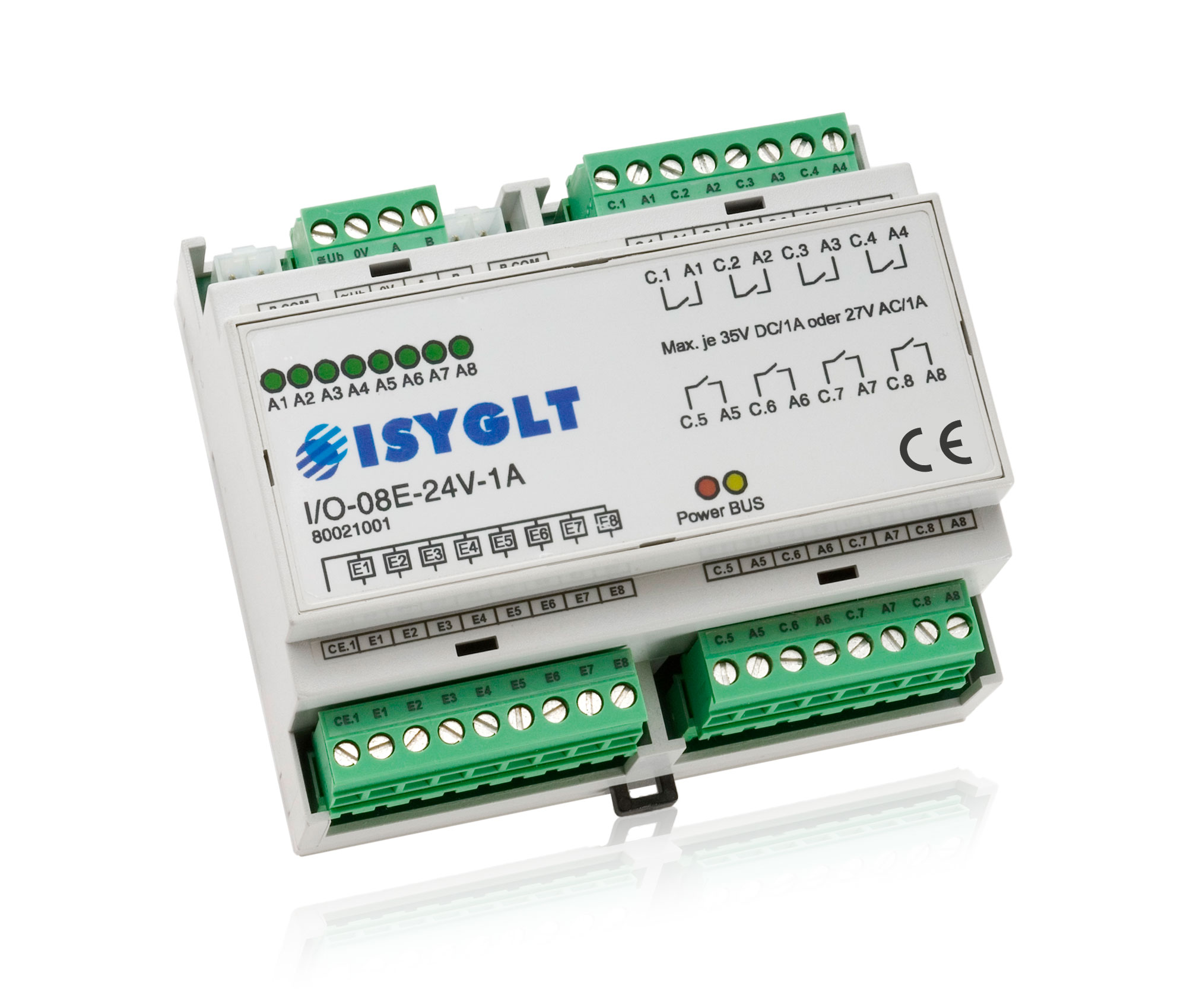
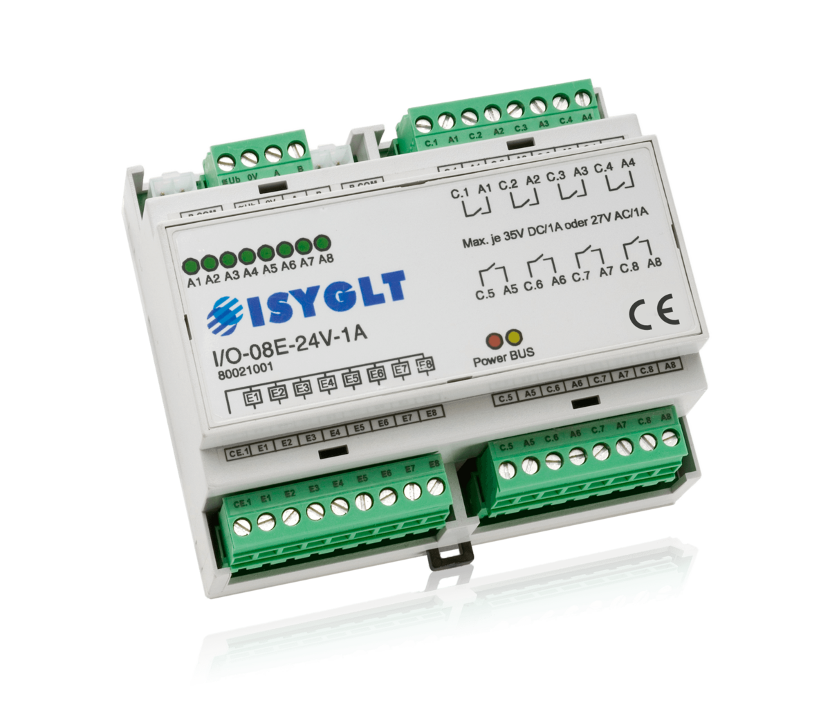
The I/O module I/O-08E-24V-1A was developed for applications with high switching frequencies. The Photomos relays used can be used to switch 8 circuits with a maximum of 5-35V DC or 5-27V AC / 1A. 
8 optocoupler inputs 12-48V on a common counter potential are available as inputs. The functions of all inputs and outputs are freely programmable via the software.

Type designation I/O-08E-24V-1A
Article no. 80021001
Operating voltage 16V to 35V DC or 16V to 27V AC
Current consumption 50mA at 24V DC (all relays are energized)
Inputs 8x 12-48V AC/DC, input current per input 5mA at 24V
Outputs 8x Photomos relay, 5-35V DC or 5-27V AC / 1A each output
Subnet (RS-485) max. 5.6V limitation by Z-diodes
Connection screw terminals 1.5mm², inputs and BUS pluggable, BUS connector
Operating temperature -10°C to +50°C
Storage temperature -25°C to +70°C
Humidity 0...85 % r.h. non-condensing
Degree of protection in not installed state IP30
Design DIN rail-mounting plastic housing light grey, snap-on on 35mm DIN rail 6 HP
Dimensions WxHxD 106x90x59mm
Weight 230g
Make ISYGLT
Conformity CE

DIP switch

8-pole DIP switch for setting the ISYGLT BUS address (0-127) is located under the cover of the module.

Special function DIP switch 1

DIP-1 Setting
OFFBUS operation
ONEmergency operation

Function Indicators (LEDs on the Module)

LED DesignationState Meaning
red POWEROff No operating voltage
OnOperating voltage, no error
yellowBUSOff / OnError BUS
blinkingInterference-free data transmission via the BUS line
8x green A1-A8Off Output inactive
On Output active

Parameterisation with ProgramDesigner

The ISYGLT ProgramDesigner offers a wide range of parameterisation options:

  • Preset behaviour after PowerOn
  • Optocoupler inputs: polarity and debouncing
  • Assign BUS inputs
  • BUS operation
  • BUS failure operation
  • Emergency operation
  • Safety functions

Pin Assignment

4-pole plug top left

Ub Operating voltage
0V Operating voltage
A Subnet (BUS A, RS-485)
B Subnet (BUS B, RS-485)

2x P-COM ports

P-COM Subnet and operating voltage

9-pole plug below left

CE.1 Common for E1-E8
E1 Input 1
E2 Input 2
E3 Input 3
E4 Input 4
E5 Input 5
E6 Input 6
E7 Input 7
E8 Input 8

8-pole plug top right

C.1 Common for output 1
A1 Output 1
C.2 Common for output 2
A2 Output 2
C.3 Common for output 3
A3 Output 3
C.4 Common for output 4
A4 Output 4

8-pole plug below right

C.5 Common for output 5
A5 Output 5
C.6 Common for output 6
A6 Output 6
C.7 Common for output 7
A7 Output 7
C.8 Common for output 8
A8 Output 8