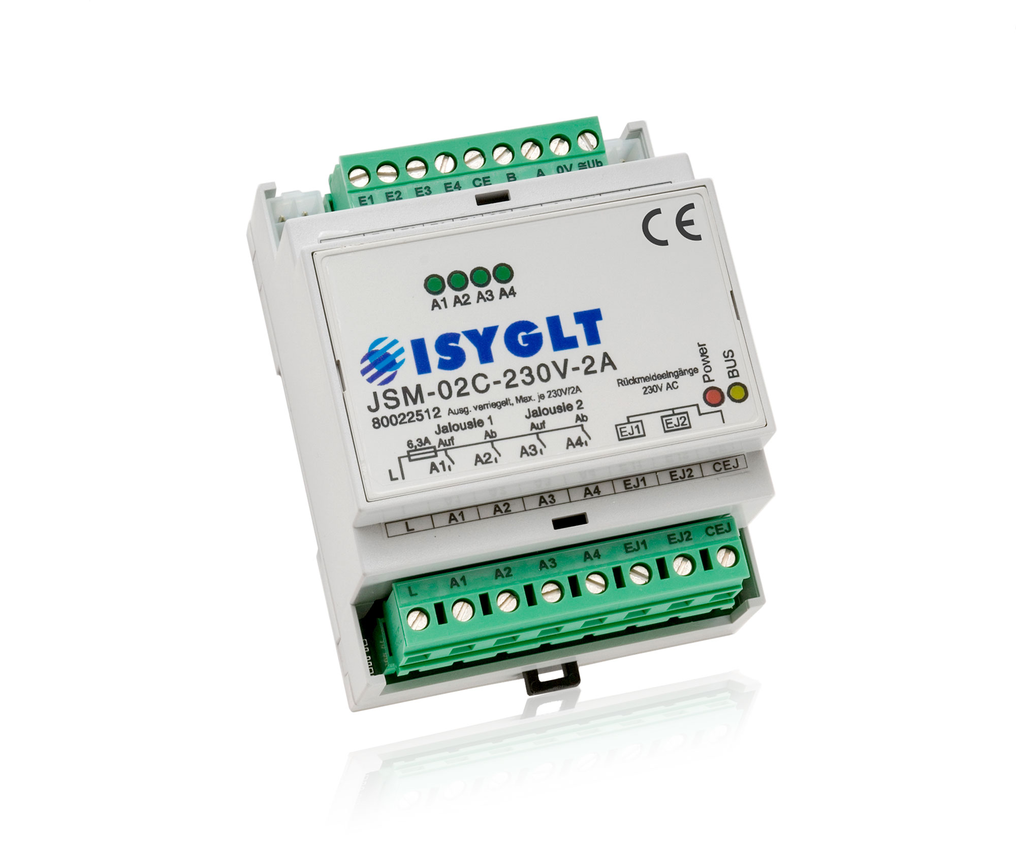
The module is used to control and position slat blinds with 230V AC motors and can operate in 3 basic operating modes:
- One blind with two motors, at the bottom for glare protection and at the top for light control (software version "LL2")
- Two blinds with one motor each as glare protection or shading (software version "VS2")
- Two vertical blinds with one motor each for glare protection and shading (software version "VJ2")
The module has 4 relay outputs (0.05 - 2A) for direct connection of the 2 blind motors. The module automatically determines the calibrated running time of the motors during each run. The slat adjustment is processor-controlled with a computer accuracy of 256 steps for the setting of 0-180°.
Programming and configuration of the blind module is very easy with our programming software ProgramDesigner (from ProgramDesigner version 4.10, Master version V4.76; Compiler V4.75). The specific parameters of the individual blinds are transferred to the blind module via the Master Module. The current signalling of the relay states for controlling both blind motors takes place via LEDs.
| Type designation | JSM-02C-230V-2A |
| Article no. | 80022512 |
| Operating voltage | 16-35V DC, 16-27V AC |
| Current consumption | max. 60mA at 24V; 80mA at 16V |
| Outputs | 4 relay outputs 250V, min. 50mA, max. 2A |
| Output voltage | 250V AC per output |
| Output current | min. 50mA (due to end position detection) max. 2A |
| Isolation voltage | outputs - BUS 1000V |
| Subnet (RS-485) | max. 5.6V limitation by Z-diodes |
| Connection | screw terminals 2.5mm², pluggable, BUS connector |
| Operating temperature | 0...+50°C |
| Storage temperature | -25...+70°C |
| Humidity | 0...85 % r.h. non-condensing |
| Protection class | IP20 |
| Design | DIN rail-mounting module 4 HP |
| Dimensions | WxHxD 71x90x59mm |
| Weight | 190g |
| Brand | ISYGLT |
| Compliance | CE |


Function Indicators (LEDs on the Module)
| LED | Designation | State | Meaning |
|---|---|---|---|
| red | POWER | Off | No operating voltage |
| On | Operating voltage, no error | ||
| yellow | BUS | Continuous Off or On | Error in BUS wiring or BUS communication |
| blinking | Interference-free data transmission via the BUS line | ||
| Fast blinking (4Hz) | Incorrect parameter memory, please retransmit parameters | ||
| 4x green | A1-A4 | On/Off | States of the relays for controlling the blind motors |
Parameterisation with ProgramDesigner
Operating modes
The Blind Control Module JSM-02C-230V-2A operates in 4 operating modes (mode 1-4), which are set by the outputs Ax.7 and Ax.8 of the Master Module.
Notice: The specifications "Register" and "Parameter" in the following text always refer to the ISYGLT Programming Software ProgramDesigner.
| Operating mode | Function | State Ax.7 | State Ax.8 |
|---|---|---|---|
| Mode 1 | Manual operation | 0 | 0 |
| Mode 2 | Automatic operation | 1 | 0 |
| Mode 3 | Set point operation | 0 | 1 |
| Mode 4 | I/O operation | 1 | 1 |
Operating mode 1 - Manual operation
This mode is used for manual driving of the blinds. The following functions are possible:
- Direct control of the output contacts by means of a programmatic link in the Master.
Example: COPY > Ax.1 = Ex.1 (Ax.1 stands for the output contact of the blind module, Ex.1 stands for a button, e.g. on site)
Pressing the button short causes an angular step (angle can be parameterised).
Pressing the button long causes the continuous run after 1 second until the limit stop or manual stop.
Pressing the button while driving causes to stop immediately. - When reversing the direction of the blind, the pause time between the direction change can be set by a time parameter (register "Jalousiemotorsetup", parameter "Verzögerung bei Richtungswechsel"). This allows the minimum pause time prescribed by the respective blind manufacturer to be observed when changing direction.
- The outputs Central Up and Down (Ax.5, Ax.6) have absolute priority (alarm, fire brigade, escape routes...). This function affects both blind motors. If, for example, „Central Up" is actuated and held, this overrides all movement functions and the blind moves upwards. The command is triggered by a pulse. The manual driving functions can also be locked with permanent contact.
- The blocking protection (register "Jalousiemotorsetup", parameter "Zeit Blockierschutz") is used to protect the blind motors. If the drive does not reach its limit stop within the set time, the contact of the module is switched off. This is signalled via the signal input Ex.7 and can be further processed in the Master. A new drive release is only possible by simultaneously pressing the up/down button, changing the mode, activating the wind/rain monitor or the central function.
- The rain protection is activated by the Master via a bit within the weather data (see description ProgramDesigner). If the rain bit is set by the Master Module, the blinds immediately move upwards (evaluation can be set in the register "Wetterschutz" with the parameter "Jalousie xx Regenschutz").
- In this mode, the wind protection is always active. The blind module receives the current wind speed and wind direction from the Master. If the wind protection is not to be evaluated, e.g. for indoor blinds, 50m/s can be entered for both wind values.
The setting parameters (see register "Wetterschutz") are the response delay time and two speeds (speed 1 and speed 2). The two speeds are assigned to the evaluation directions (N, NO, O, SO, S, SW, W, NW). In this way the blinds can be protected facade by facade, depending on the wind direction, without all blinds having to be moved upwards immediately.
If the wind speed exceeds the set thresholds and delay times, the blinds automatically move upwards and remain locked until the wind speed falls below the set threshold. When the wind protection is activated, the blocking protection is automatically reset. If the measured wind speed is twice as high as the set threshold value, the wind protection is activated without time delay.
The locking by the wind protection is reported to the BMS system (Ex.6).
Operating mode 2 - Automatic operation
In this mode, the blind is moved fully automatically and the slat angle is adjusted. The following functions are possible:
- The blind is lowered when all conditions in Table 1 (see below) are given or when all conditions in Table 2 are given. Table 2 has a higher priority. If both conditions (Table 1 and Table 2) are given, the slat angle is always calculated by the condition of Table 2 (forced shading). This function is identical for both blinds, but the parameters can be set individually.
If none of the conditions is fulfilled, the blind moves to the defined starting position "Top" or "Below" with a defined angle and a definable night position (parameter in the register „Allgemein"). See also "Special functions in automatic operation". - When reversing the direction of the blind, the pause time between the direction change can be set by a time parameter (register "Jalousiemotorsetup", parameter "Verzögerung bei Richtungswechsel"). This allows the minimum pause time prescribed by the respective blind manufacturer to be observed when changing direction.
- The outputs Central Up and Down (Ax.5, Ax.6) have absolute priority (alarm, fire brigade, escape routes...). This function affects both blind motors. If, for example, „Central Up" is actuated and held, this overrides all movement functions and the blind moves upwards. The central functions must be programmed as permanent contacts. The motors run as long as the command is pending and stop when it is cancelled.
- The blocking protection (adjustable via the parameter "Zeit Blockierschutz" in the register "Jalousiemotorsetup") is used to protect the blind motor. If the drive does not reach its limit stop within the set time, the contact of the module is switched off. This is signalled via the signal input Ex.7 and can be further processed in the Master. A renewed run release is only possible by a mode change or the response of the wind/rain monitor.
- The rain protection is activated by the Master via a bit within the weather data (see description ProgramDesigner). If the rain bit is set by the Master module, the blind moves upwards immediately.
- In this mode, the wind protection is always active. The blind module receives the current wind speed and wind direction from the Master. If the wind protection is not to be evaluated, e.g. for indoor blinds, 50m/s can be entered for both wind values.
The response delay time and two speeds (speed 1 and speed 2) are provided as setting parameters. The two speeds are assigned to the evaluation directions (N, NO, O, SO, S, SW, W, NW). In this way the blinds can be protected facade by facade, depending on the wind direction, without all blinds having to be moved upwards immediately.
If the wind speed exceeds the set thresholds and delay times, the blinds automatically move upwards and remain locked until the wind speed falls below the set threshold. When the wind protection is activated, the blocking protection is automatically reset. If the measured wind speed is twice as high as the set threshold value, the wind protection is activated without time delay.
The locking by the wind protection is reported to the BMS system (Ex.6).
Table of conditions 1: All conditions in the table are AND functions.
| No. | Meaning | Parameter | Register |
|---|---|---|---|
| 1 | The azimuth (direction from which the sun shines) must lie between the left and right edges of the window. | Azimut Begrenzung links Azimut Begrenzung rechts | Blendschutz |
| 2 | The elevation (elevation angle of the sun above the horizon) must lie between the lower and upper viewing angle limits of the window. | Elevation Begrenzung unten Elevation Begrenzung oben | Blendschutz |
| 3 | The wind protection must not be active. | Wetterschutz | |
| 4 | The preset shading light intensity must be reached. | The calculation of the shading light intensity is described later. | Beschattung |
Table of conditions 2: All conditions in the table are AND functions.
| No. | Meaning | Parameter | Register |
|---|---|---|---|
| 1 | The wind protection must not be active. | Wetterschutz | |
| 2 | One of the two forced shading light intensities must be reached. | Beschattung |
Slat angle calculation if the conditions in Table 1 are fulfilled
For the calculation there is a parameter table, which contains the slat angles in dependence on the elevation (elevation angle of the sun over the horizon).
The resolution of this table is 10°, related to the elevation. Thus for all elevation values from 0 to 90°, at a distance of 10°, a corresponding slat value can be stored. If the sun is between the elevation values graded in 10°, the slat angle is interpolated. Thus, different driving strategies can be realized depending on the elevation. By default, the table values are set so that the slats are always at 90° to the sun, i.e. provide the greatest possible glare protection. If the blind is to allow some sunlight through even when the sun is shining, the following values (register "Blendschutz") have proved their worth:
| Parameter | Slat angle |
|---|---|
| Elevation 0 grd | 15 grd |
| Elevation 10 grd | 25 grd |
| Elevation 20 grd | 35 grd |
| Elevation 30 grd | 45 grd |
| Elevation 40 grd | 55 grd |
| Elevation 50 grd | 65 grd |
| Elevation 60 grd | 75 grd |
| Elevation 70 grd | 85 grd |
| Elevation 80 grd | 90 grd |
| Elevation 90 grd | 90 grd |
To include indirect glare, e.g. from opposite window surfaces, in the shading or glare protection, there are still 5 glare areas available in the register "Blendschutz".
| Parameter | Value |
|---|---|
| Art Steuerung Lamelle | Direkt Elevation (or fixed angle) |
| Azimut Begrenzung links | e.g. 90 grd |
| Azimut Begrenzung rechts | e.g. 35 grd |
| Elevation Begrenzung unten | e.g. 1 grd |
| Elevation Begrenzung oben | e.g. 90 grd |
To implement daylight control systems, the correct slat angle for the respective elevation angle must be specified by the manufacturer of the blind or determined by testing (e.g. in manual operation).
Slat angle calculation if the conditions in Table 2 are fulfilled
The slat angle assigned to the respective forced shading light intensity is approached. The activation of forced shading is reported back to the BMS system.
Calculating the shading light intensity
The currently measured brightness value of the light sensor from the set evaluation direction is used for calculation. To avoid swinging, the delay time for shading and unshading can be set separately. The measured outdoor light value is smoothed by a time filter. The outdoor light value can also be changed by the BMS system. The scaling of the outdoor light value is enabled in the register "Allgemein". This option is intended for special applications. For standard applications, this parameter should be set to "nicht verwenden".
| Parameter | Register |
|---|---|
| Ansprechzeit (Verzögerungszeit) (Sekunden) Verschatten | Allgemein |
| Ansprechzeit (Verzögerungszeit) (Sekunden) Entschatten | Allgemein |
| Auswerterichtung Lichtwert | Beschattung |
The limit value of the shading light intensity depends on the current elevation. If the elevation is less than 0°, the shading light intensity is automatically considered not to have been reached.
The light threshold value is determined from the following 4 elevation limit values:
| Parameters to be used | Value | Register |
|---|---|---|
| Elevation 0 bis 9 grd | 3 klx | Blendschutz |
| Elevation 10 bis 29 grd | 10 klx | Blendschutz |
| Elevation 30 bis 59 grd | 30 klx | Blendschutz |
| Elevation 60 bis 90 grd | 40 klx | Blendschutz |
Special functions in "Automatic operation"
Parking position:
In "Automatic operation", the blind can be moved to a predefined slat angle if one of the above conditions is not met. The blind can thus be lowered generally during the day, for example, even if the outside light is lower than the specified threshold value.
Night position:
If the outdoor light value defined in the parameter is not reached and after the specified time has elapsed, the blind can, when enabled (parameter), assume an angle defined by parameter (see register "Allgemein").
Operating mode 3 - Set point operation
In this mode the blind slat angle is adjusted by the Master. This is required if, for example, cleaning positions or separately programmable controls are to be implemented in which the slats are to be set to defined angles.
- The blind slat angles are specified directly by the Master for both blinds via the AAx.1 analog control channel. The values 0-180 correspond to the angle positions 0-180°. The 0° position is closed, at the bottom. If the value is 255, the blinds move upwards.
Control pulses (readjust the slats) are only output to the blind if the difference between the setpoint angle and the actual value angle is greater than the angle value specified in the parameter. - When reversing the direction of the blind, the pause time between the direction change can be set by a time parameter. This allows the minimum pause time prescribed by the respective blind manufacturer to be observed when changing direction.
- The outputs Central Up and Down (Ax.5, Ax.6) have absolute priority (alarm, fire brigade, escape routes...). This function affects both blind motors. If, for example, "Central Up" is actuated and held, this overrides all movement functions and the blind moves upwards. The central functions must be programmed as permanent contacts. The motors run as long as the command is pending and stop when it is cancelled.
- The blocking protection (adjustable via the parameters in the register "Jalousiemotorsetup") serves to protect the blind motor. If the drive does not reach its limit stop within the set time, the contact of the module is switched off. This is signalled via the signal input Ex.7 and can be further processed in the Master. A renewed run release is only possible by a mode change or the response of the wind/rain monitor.
- The rain protection is activated by the Master via a bit within the weather data (see description ProgramDesigner). If the rain bit is set by the Master Module, the blinds move upwards immediately (evaluation can be set with parameters).
- In this mode, the wind protection is always active. The blind module receives the current wind speed and wind direction from the Master. Setting is possible separately for both blind motors. If the wind protection is not to be evaluated, e.g. for indoor blinds, 50m/s can be entered for both wind values.
The response delay time and two speeds (Speed 1 and Speed 2) are provided as setting parameters. The two speeds are assigned to the evaluation directions (N, NO, O, SO, S, SW, W, NW). In this way, the blinds can be protected facade by facade, depending on the wind direction, without all blinds having to be moved upwards immediately.
If the wind speed exceeds the set thresholds and delay times, the blinds automatically move upwards and remain locked until the wind speed falls below the set threshold. When the wind protection is activated, the blocking protection is automatically reset. If the measured wind speed is twice as high as the set threshold value, the wind protection is activated without time delay.
The locking by the wind protection is reported to the BMS system (Ex.6).
Operating mode 4 - I/O operation
In this mode the module works like a normal switching module.
- The outputs are addressed directly by the Master. Even in this mode, both outputs (Up and Down) cannot be active simultaneously, as the relay outputs are additionally locked against each other on the hardware side. If both outputs are set, the blind module switches off both relay contacts.
- No central function
- No blocking protection evaluation
- No rain monitor evaluation
- No wind monitor evaluation
Register "Synchronisation"
In general, each blind module works independently. During commissioning, the parameters determine where the blind is located and which positions of the sun are to be expected. The module determines its driving strategies from the weather data supplied via the BUS. If several modules are in operation on one side of the facade, they may work with a slight delay. To prevent this, a module can be used for synchronisation.
| Parameter | Value |
|---|---|
| Art Steuerung Lamelle | Direkt Elevation (or fixed angle) |
| UP/DOWN-Sync Jalousie 1 | Ein/Aus |
| UP/DOWN-Sync Jalousie 2 | Ein/Aus |
| Blind module, to which is synchronised | Adr. xxx Jx |
Additional Equipment
SUN-PRO-01 - Sensor for sun position
WETTER-01 - Weather Station with sun position and brightness from 4 directions
ZTLS-04 - Central Daylight Sensor
JSM-02C-230V-2A
Article no.: 80022512