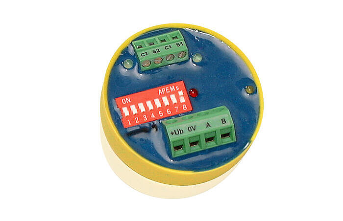
The Temperature Module is used to read in 2 temperatures using the separately available digital Temperature Sensor TF-xx. These values can be further processed in the Master Module, so that temperature-dependent control and regulation can be implemented. Application areas for this are: Control cabinet temperature monitoring, outdoor temperature measurement, room temperature measurement...
| Type designation | TEMP-02U |
| Article no. | 80080300 |
| Operating voltage | 12-27V DC / 16-24V AC |
| Current consumption | max. 22mA (DC) 35mA (AC) |
| Measuring range | 2 inputs for sensor connection from -50°C to +105°C |
| Temperature sensors | max. 2x TF-**, length of cable to sensor max. 20m |
| Subnet (RS-485) | max. 5.6V limitation by Z-diodes |
| Connection | screw terminals 2.5mm² for BUS, pluggable screw terminals 1.0mm² for sensor |
| Operating temperature | -10...+50 °C |
| Storage temperature | -25...+70°C |
| Humidity | 0...85 % r.h. non-condensing |
| Protection | IP 40 |
| Design | encapsulated in yellow plastic cap for installation in boxes or external devices |
| Dimensions | DxH 50 x 28 mm |
| Weight | approx. 90 g |
| Brand | ISYGLT |
| Compliance | CE |


Function Indicators (LEDs on the Module)
| LED | Designation | State | Meaning |
|---|---|---|---|
| red | Power | Off | No operating voltage |
| On | Operating voltage, no error | ||
| yellow | BUS | Off / On | Error BUS |
| blinking | Interference-free data transmission via the BUS line | ||
| 2x green | Sensor | Off / On | No sensor or sensor incorrectly connected |
| blinking | The respective sensor works correctly |
Measuring ranges
Like the analog value of an analog input module, the temperatures are transferred to flags with the TRFAD command. Input AE1 corresponds to sensor 1 and input AE2 to sensor 2. In addition, the digital inputs of the temperature module can be read. Bits 1 and 2 indicate the readiness messages (E1 = 1: sensor 1 ready, E2 = 1: sensor 2 ready) of the sensors.
These bits are only set to 1 if a functional sensor is connected to the corresponding input.
Inputs 3 and 4 (E3 for sensor 1 and E4 for sensor 2) indicate the negative sign of the probe temperatures. The sign bit of a sensor is set when the measured temperature at the sensor is less than 0°C, regardless of the measuring range with which the sensor is configured.
Note: The sign of the sensor temperature can be read at the digital inputs E3 (sensor 1) and E4 (sensor 2).
| Config. as module | Reference temperature 1 | Reference temperature 2 | Reference temperature 3 | Flag measured value 1 | Flag measured value 2 | Flag measured value 3 | Resolution | Remark |
|---|---|---|---|---|---|---|---|---|
| TF1 | no measurement | 0 °C | + 105°C | 0 | 0 | 105 | 1°C / digit | Limited below 0°C |
| TF2 | -50 °C | 0 °C | + 105°C | 50 | 0 | 105 | 1°C / digit | Sign bit must be evaluated |
| TF3 | -50 °C | 0 °C | + 105°C | 0 | 50 | 155 | 1°C / digit | Offset of +50°C; therefore an evaluation of the sign bit is not necessary |
| TF4 | -50°C | 0 °C | + 105°C | -50 (206) | 0 | 105 | 1°C / digit | Display as signed 8-bit number (two's degree -128 to +127) |
| TF5 | no measurement | 0 °C | + 105°C | 0 | 0 | 210 | 0,5°C / digit | Limited below 0°C |
| TF6 | -50°C | 0 °C | + 105°C | 100 | 0 | 210 | 0,5°C / digit | Sign bit must be evaluated |
| TF7 | -25°C | 0 °C | + 100°C | 0 | 50 | 250 | 0,5°C / digit | Offset of +25°C; therefore an evaluation of the sign bit is not necessary |
TEMP-02U
Article no.: 80080300


